Insight Chips' Nano Channel Chips feature mixing of liquids directly in the field of view. In this application note, the experiment is described in detail, showcasing easy mixing and the resulting observations of in situ crystal growth.
Mixing of CaCl2 and Na2CO3 in concentrations of 6 mM of each was performed using our Nano Channel Chips.
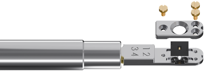
The chip used was a B37W1 (batch #37, wafer #1) chip with the following specs:
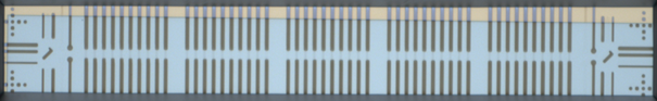
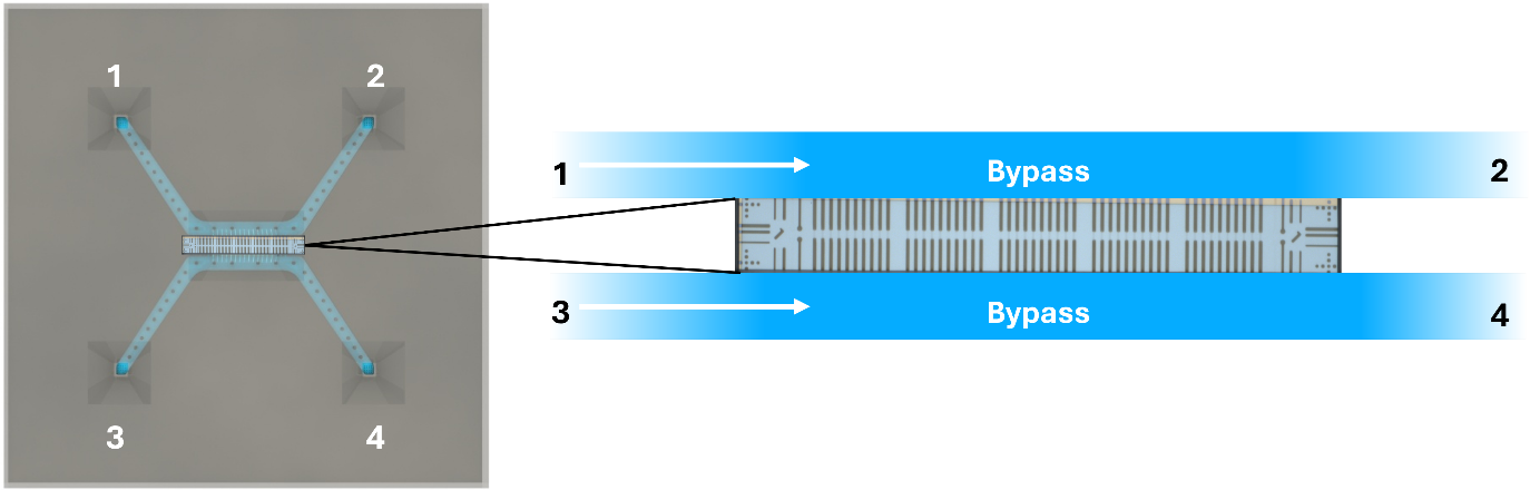
The inside of the chip has a standard configuration of 4 inlets and 2 bypass channels, connecting inlet 1 with 2, as well as 3 with 4.
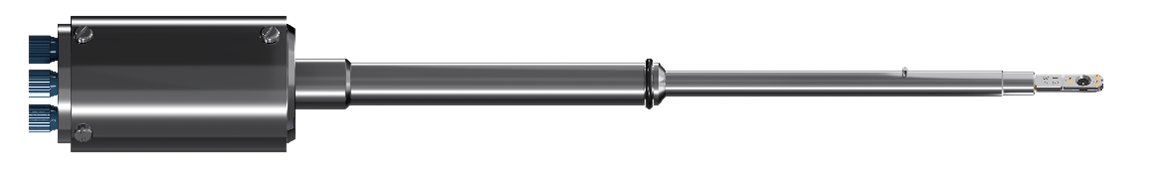
Our Thermo Fisher compatible TEM holder with 4-inlet flow control.
The chip and holder are used in combination to mix liquids during a TEM session as seen in the video here.
Tecnai T20 G2 equipped with a TVIPS XF416 CCD camera.
The TEM is operated in extreme under-focus during all imaging presented in this app-note, to enhance contrast as much as possible when observing low- to medium range magnification of CaCO3 precipitates.
The chips used in this experiment are quite unique, as they did not turn out as intended in the batch. However, as it turns out, they are great at this type of experiment where the mixing of two liquids in sequence is needed.
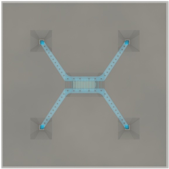
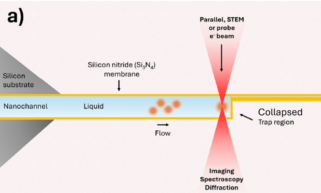
What makes the chips unique is that they were supposed to work to trap nanoparticles in a confining region of the chips, as illustrated in the figure below.
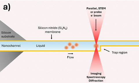
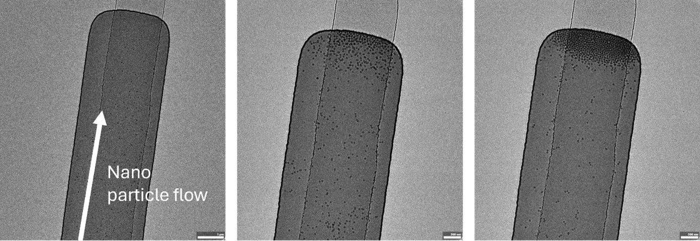
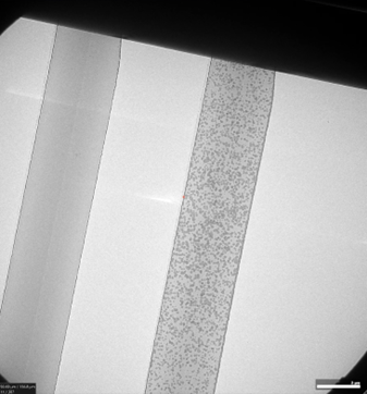
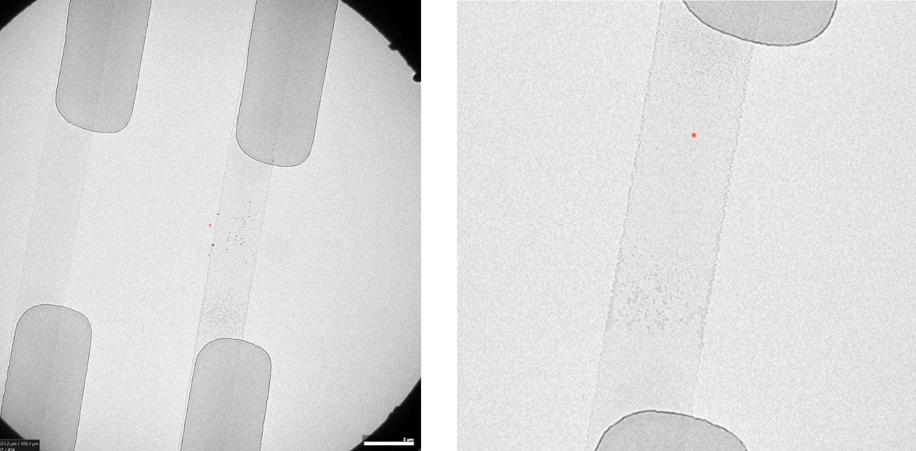
These chips normally work by allowing a flow through the entire channel, including the confining part, so the flow will continue to bring new particles to the channel, which will get stopped once approaching the confined region. An example is given in the image below, where 50 nm SiO2 particles are being flowed in continuously throughout the experiment, getting trapped in the confined region.
You can read more about these traps in our published paper titled “In-situ liquid phase TEM of trapped nanoparticles: native-state observation and structural characterization” which you’ll find here.
What happened with the unique chips used in this work is that the trapping region was made too thin, 1-5 nm, resulting in a collapse and, therefore, hindering liquid flow and particle trapping.
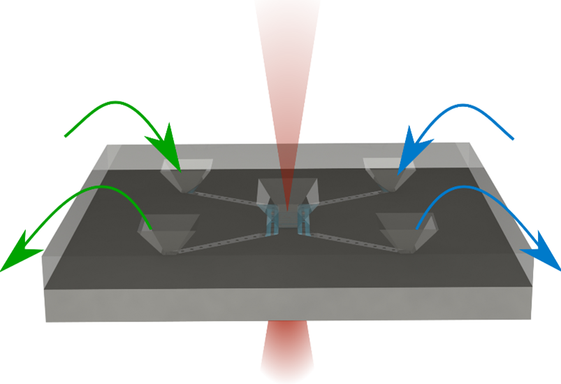
Instead, a new way has been found to use these chips, which is to flow liquids into the same micro bypass channel one by one, sequentially, each time diffusing into the visible nano channel region and reacting with the liquid already there.
The principle is outlined in the figure below.
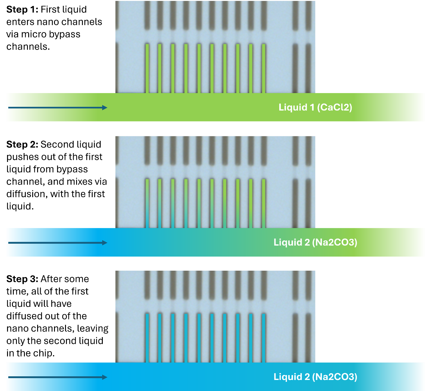
The method of sequential mixing can be repeated numerous times, in both bypass channels.
Each time the liquid is exchanged, a time window of ideal concentration will exist in the nano channels until the first liquid has been completely diffused out of the channels and exchanged with the second liquid.
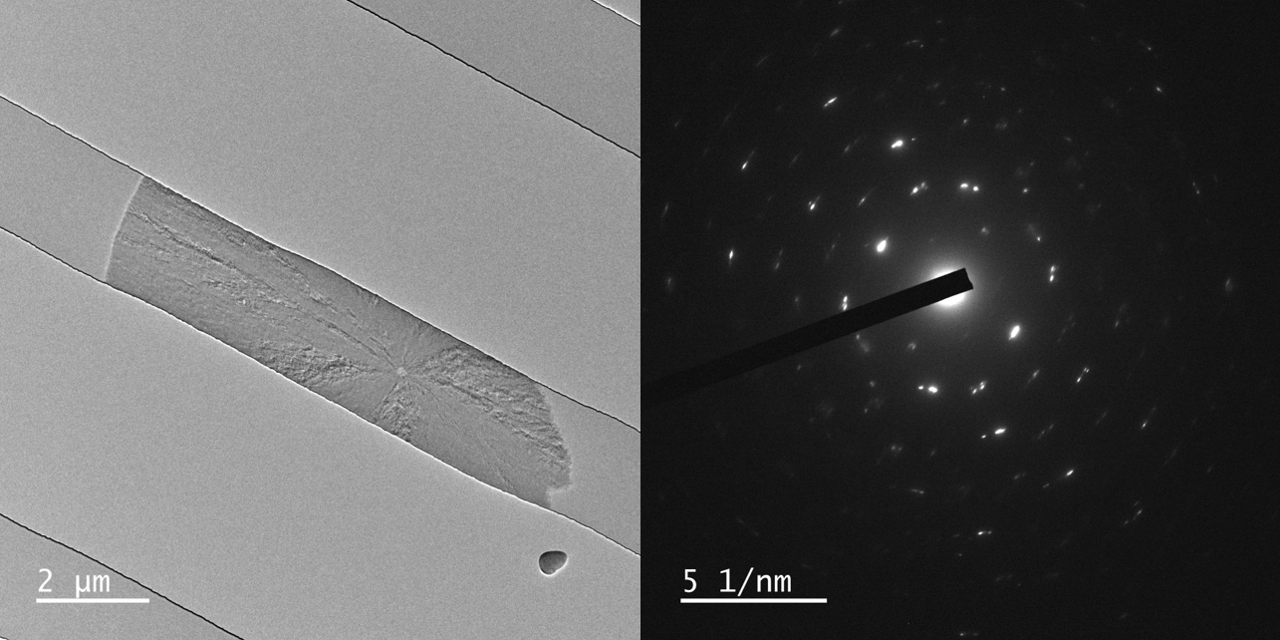
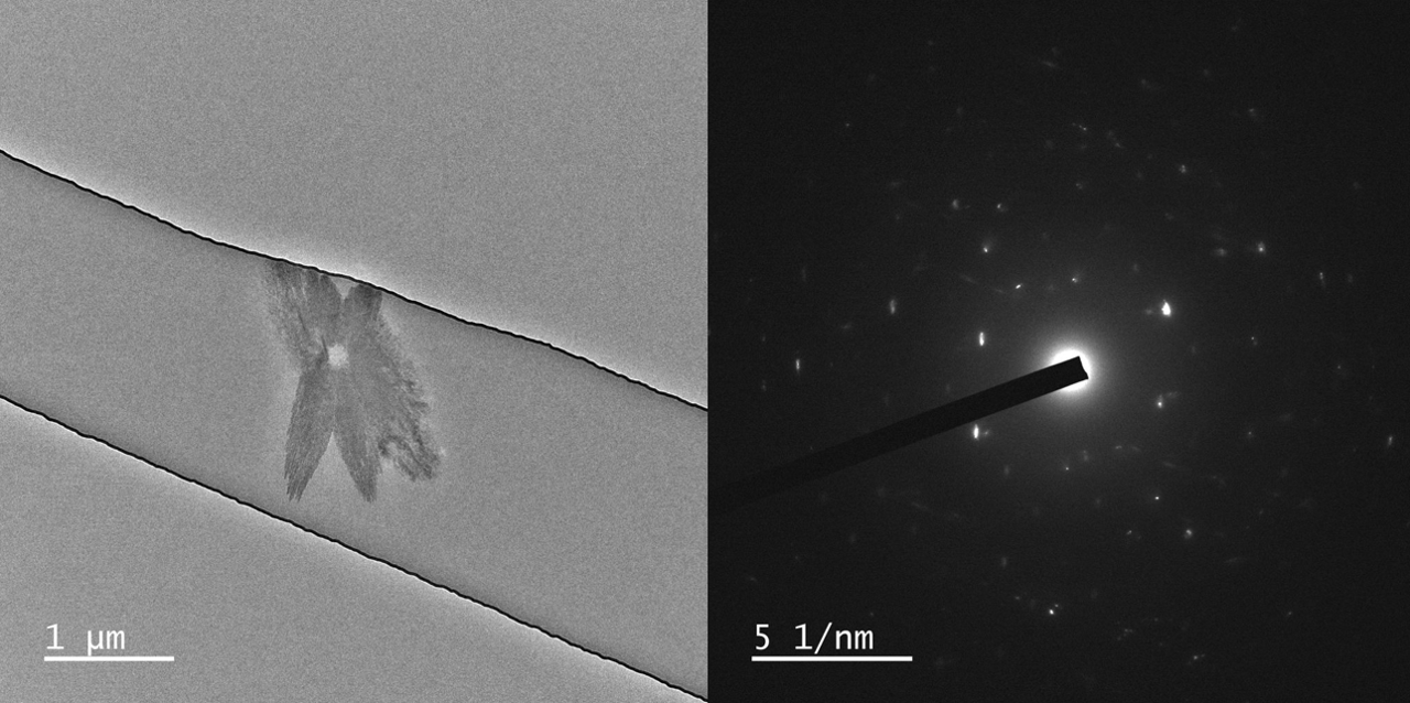
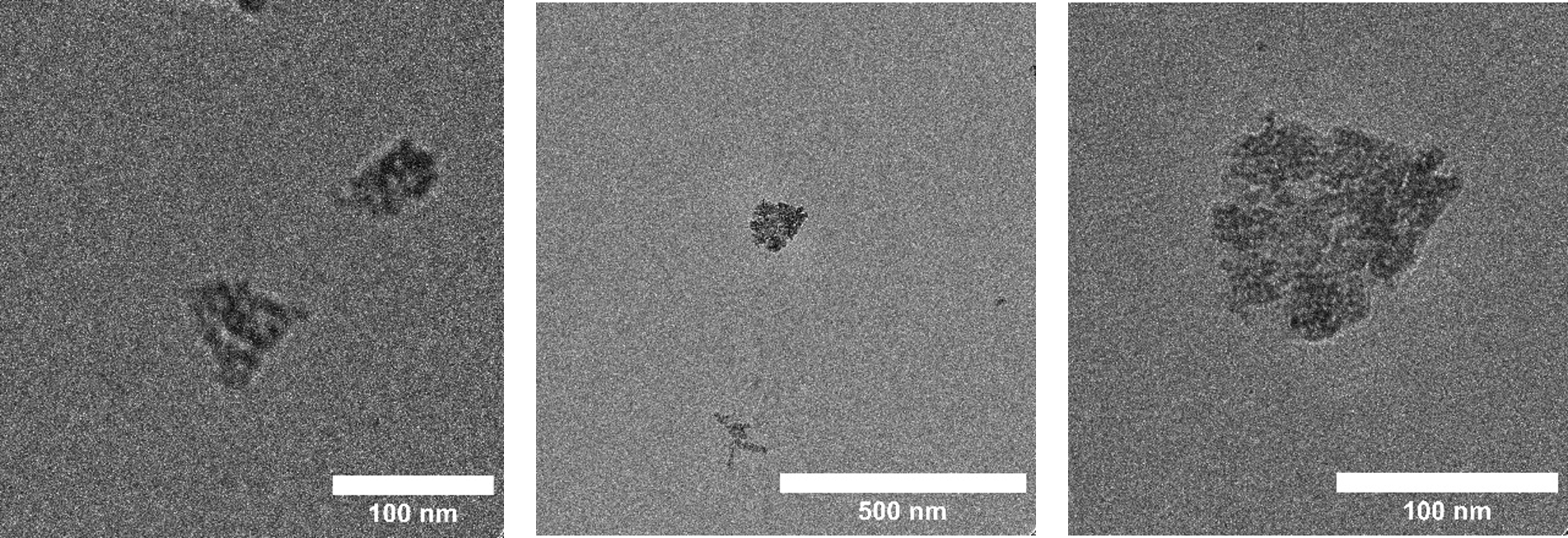
In the case of CaCO3, the particles will grow when there is about an even mix of CaCl2 and Na2CO3 and then dissolve again when either of the liquids are predominant.
Therefore, in this experiment, each liquid was flushed in sequentially, over 10 times, and particles were seen grow and dissolve over and over again.
In the end, mixed liquid had flown through the tubing in the holder and grown CaCO3 crystals inside it. As a result, fluidic resistance built up the holder, making it hard to flow any more liquid through. The solution to this was to inject 15 w.t.% citric acid, which completely dissolved the crystals in the nano channels, which was recorded in the TEM, as well as in the tubing in the holder. After a few seconds of injecting this mild acid, the liquid was flown through the holder again with ease.
A caveat to the process of sequential mixing described above is that the trap regions, although collapsed, do let in a very small amount of liquid. Therefore, liquid does enter this region a little bit, and as results will show, CaCO3 crystals are also seen grow here!
This caveat is not undesired, as it reveals what the crystals look like in liquid that is almost zero nanometers thin, perhaps around 1-2 nm. Due to this extreme thinness, resolution will be the absolute highest in this region.
In all regards, the experiment works according to the sequential mixing method described above, but additionally, crystals can be seen grow in the collapsed trap region.
(Result update October 4th, 2025)
With courtesy of Prof. Yuki Kimura and Dr. Tomoya Yamazaki from the Institute of Low Temperature Science at Hokkaido University we have some images of crystals grown in three different liquid thicknesses, <5 nm, 60 nm, and 150 nm. All SiN membranes are 17 or 19 nm on both top and bottom.
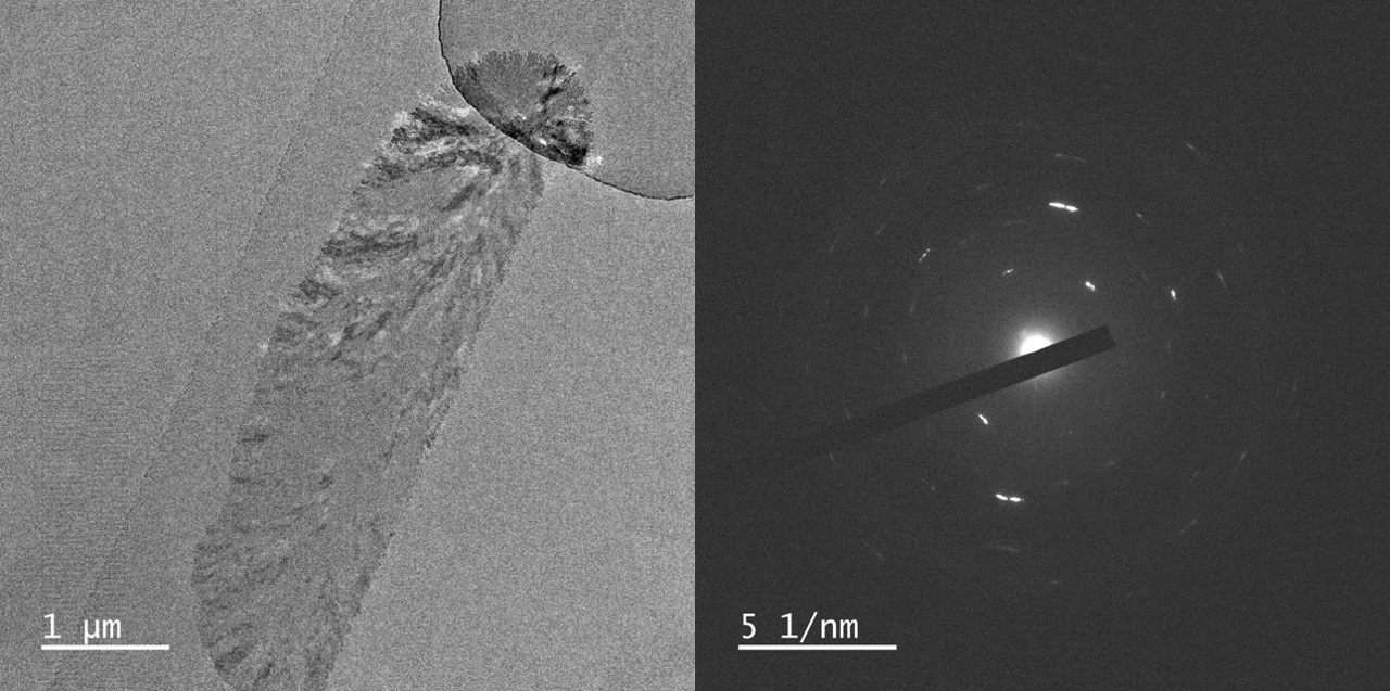
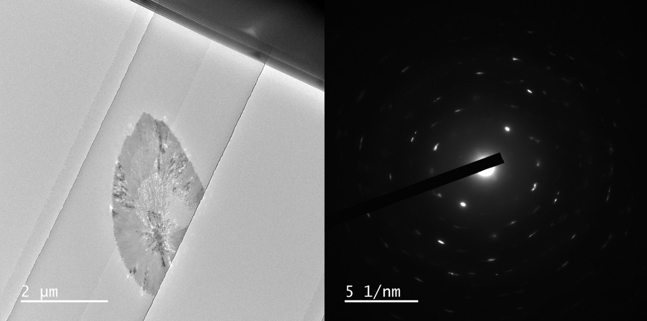
Various polymorphs of CaCO3 exists, such as aragonite, calcite, and vaterite which are all crystalline. Further, amorphous CaCO3 can form as well.
In these results different morphologies were observed, although it was not investigated further, which polymorphs grew in the nano channels.
To finish off the experiment, 15 wt.% citric acid was used to dissolve the CaCO3 both in the nano channels, and in the tubing in the holder.
This experiment has been performed 4 times, and the result has been similar every time. The experiment can therefore be regarded as a nice demo-experiment, showcasing both the ease of use of Insight Chips' holders and Nano Channel Chips, as well as the potential of mixing two liquids together in the field of view.
The setup also serves as a protocol which can be used for other mixing experiments, as it is reproducible and robust.
Going forward, it would be interesting to
Insight Chips is always happy to go to your lab to continue to research and expand our collaborations.
Let us know if you are interested!